
The system
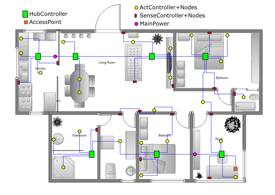
The system contains different modules to start with and you can always add your own. The general setup is the following. We have a topology free network (not a bus) throughout the house. This consists of cat5 cable. Connected to this network are several controllers, which are, in turn, connected to sensors or actuators. There is one (or if needed more) 48V=/1A power supply, and depending on the network structure one or more power converters (48V= to 5V=). Somewhere on the network there is an access point which makes it possible to configure the system. On central places distribution controllers (hubs) may be located to increase the number of connected nodes. Normally you would connect HubControllers with each other and sensor and actuator controllers to the hubs, but this is not strictly required. Since the sensor and actuator controllers have two network connections, they can be used to link the network also. Sometimes this is more convenient.
The actuator controllers can operate up to four lights, machines etc. through a dimmer node, switch node or relay node. Then we have the sensor controllers which can be coupled to a rotary encoder or a direction sensitive capacitive sensor. A collection of lights or switches is drawn as one in the figure. The access controller has an ethernet connetion, which can be connected to the PC directly or to any network switch.
The intelligence is distributed over the network. That is, any controller runs it own small operating system (Femto OS) with a shell. The system can be configured by logging in to the controllers and issuing commands. No central PC is needed for everyday operation. The access controller can send out messages over the tcp/ip network when connected.
| Contact: info@templetronics.org | CC-BY-NC-SA License: Ruud Vlaming. |