
Construction of first Prototypes
The prototypes form a collection to test the concepts of TempleTronics home automation. Remember, this is an open source hardware project, and you are invited to build along. The prototypes are not yet fully functional systems, but one step in the right direction.
Minimal system
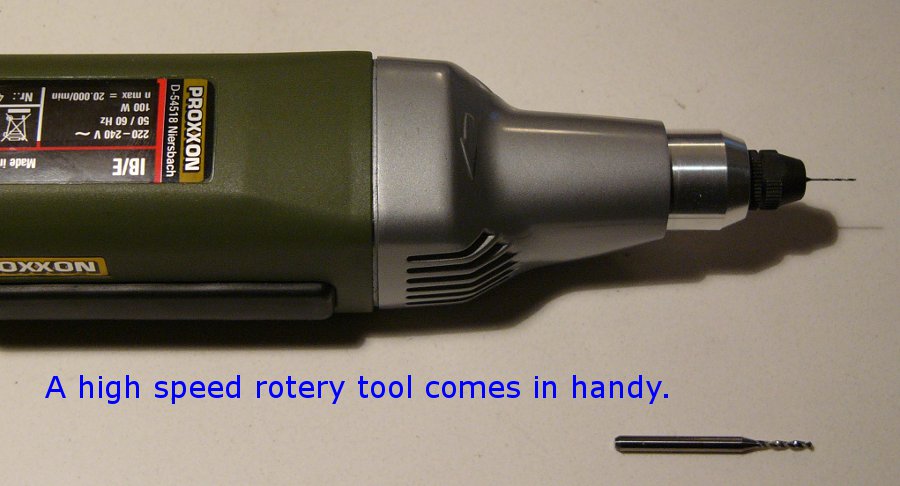
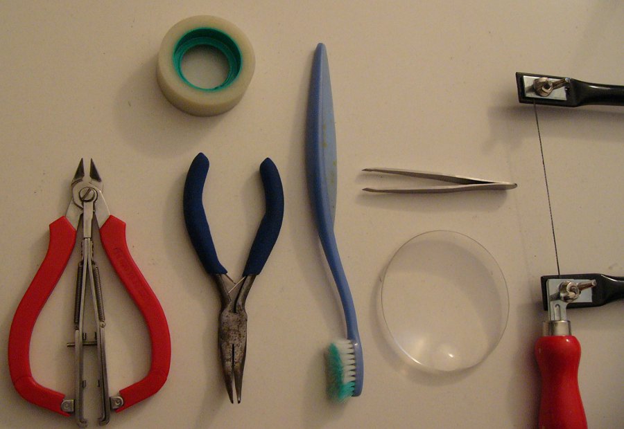
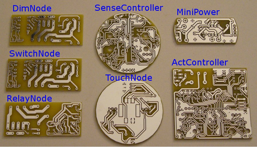
The minimal system consists of some actuator nodes, an actuator controller, one or more sensor nodes and an sensor controller. Power can be drawn for a separate power supply for the moment. To construct these nodes, only simple tooling is needed. If you are not in your twenties any more, a magnifying glass is nice to have. Of course, you need to solder too. The PCB's are mostly double sided. Note they do not have a silk screen since these are prototypes (and expensive enough already!)
MiniPower
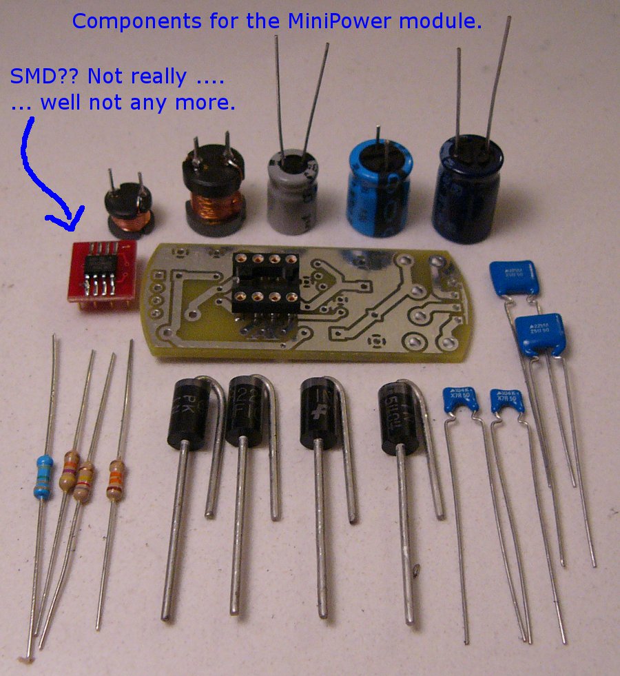
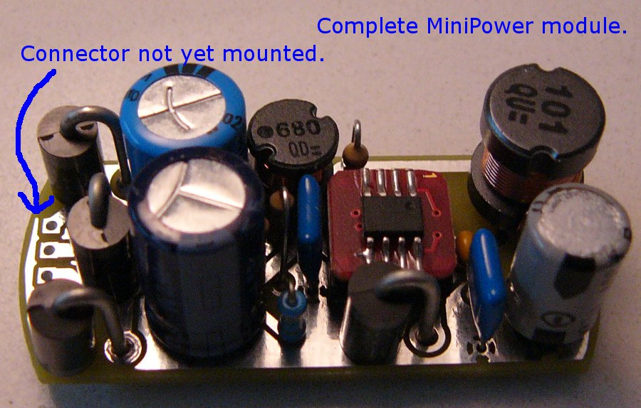
The system is power from 48V=. These has to be transformed locally to 5V=. I have designed the power converter for that, called MiniPower, and this works too, but I am not satisfied yet. First of all, it is bulky and its efficiency is not too high, especially at low load. Further, it is costly too. These two reasons imply that you must share the generated power over several nodes in the neighbourhood. Possible, but it would be much better if we had a (non smd) way to step down on every controller. BTW, the smd component on the photo can be ordered in DIL too, but not in small quantities. If a suitable component can be found that directly converts 48V= to 5V= that would be a big gain!
SwitchNode / DimNode
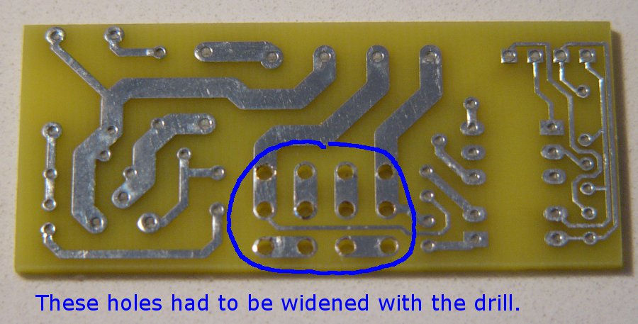
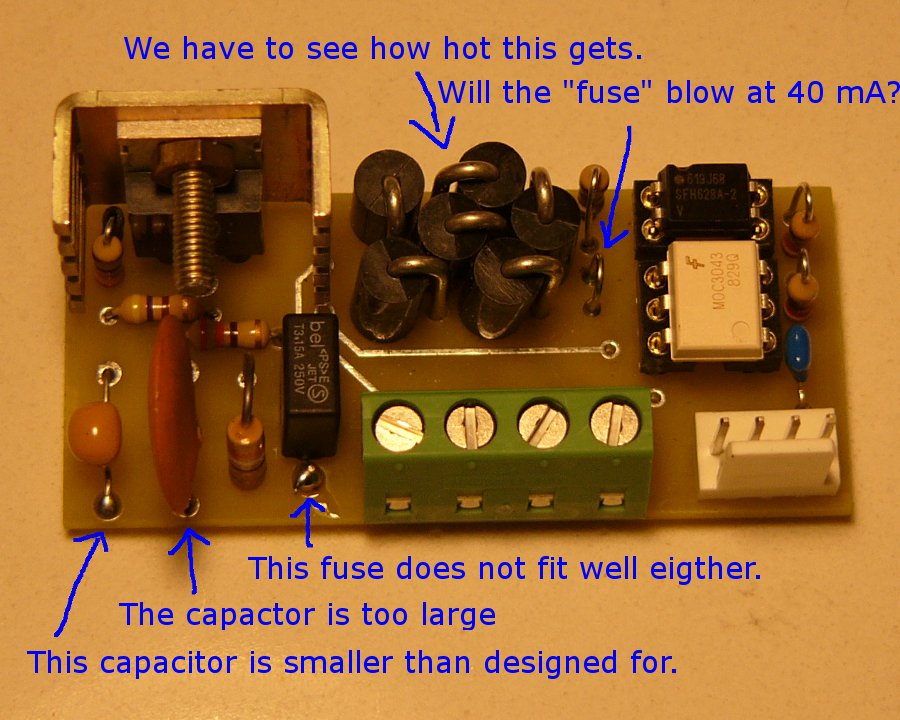
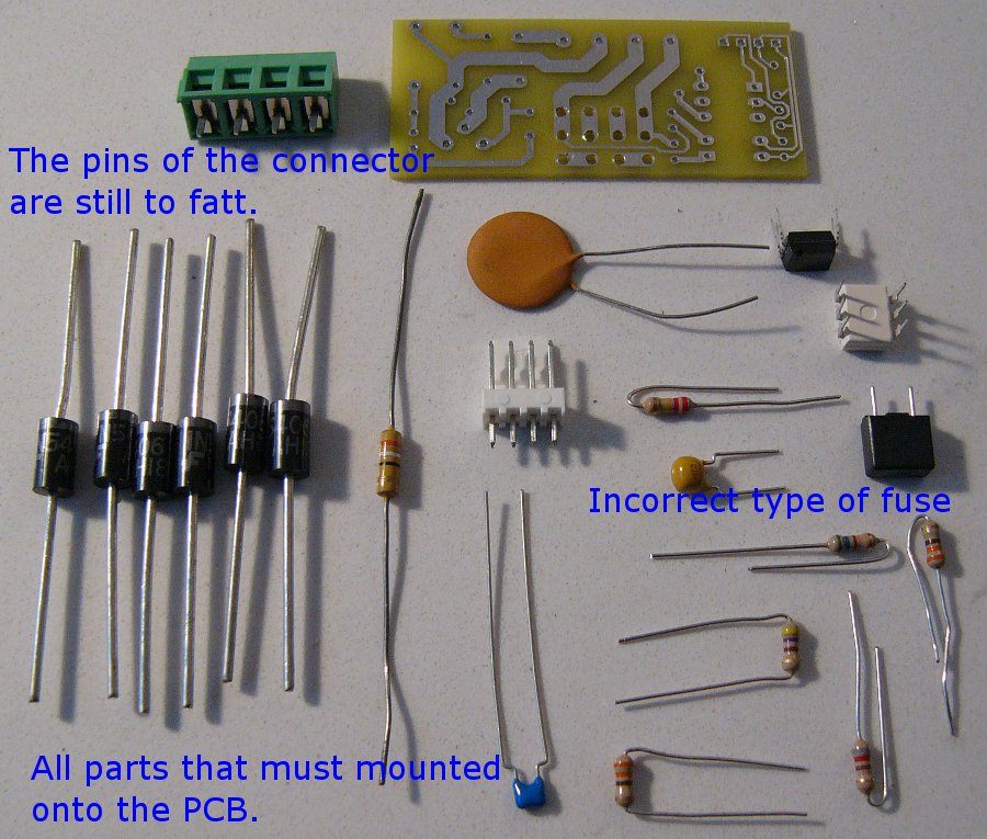
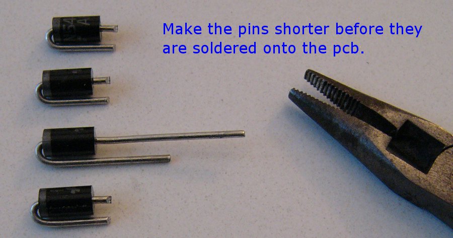
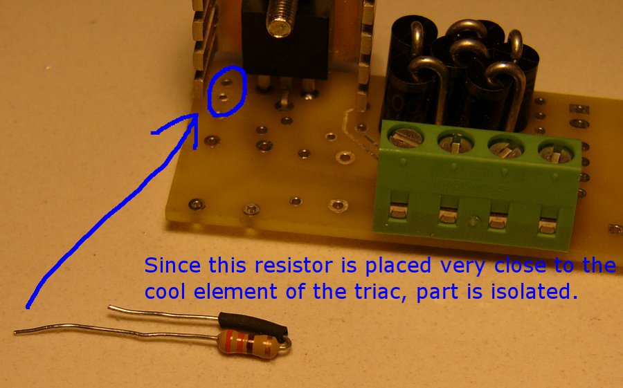
The DimNode and SwitchNode both have the same PCB. In the design of that PCB the holes for the diodes were too small, so they had to be increased. Of course the next version PCB will be corrected. The construction is very very compact, We have to see if the heat can be properly dispersed. Of course, we fuse it at 3A and recommend operation is up to 2A. (Which should be enough for any regular lamp).Hot and cold sides are separated. Note that the (green) mains connector has its connection points to the inside, this is to reduce space requirements. In the next design I will displace the triac a little so it comes more to the centre if possible. And note that the capacitors are NOT the ones which will be used in the end design, since they do not have the proper ac high voltage rating.
RelayNode
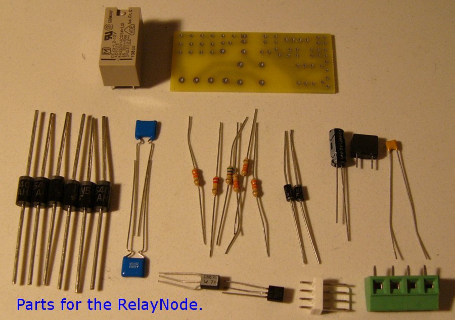
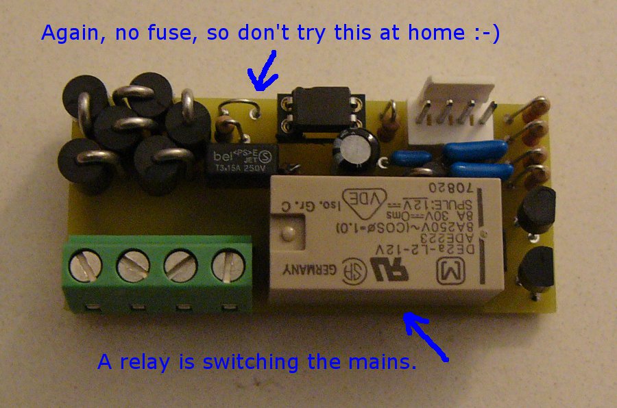
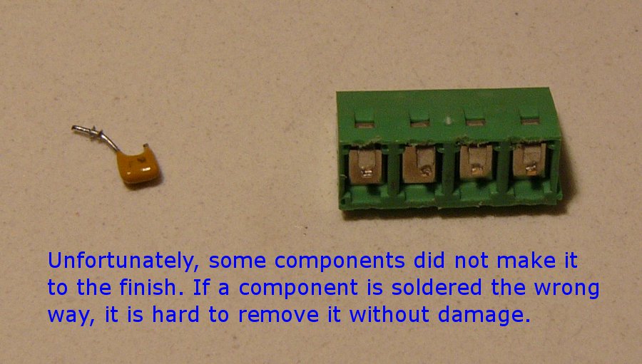
The RelayNode is meant for situations that cannot be switched with a track. Although the relay is able to switch 8A, it does so only at cos(phi)=1. Thus, no heavy inductive loads please. But for the smaller loads it is nice to have. While building this node I was distracted, and thus two components died. Removing them without doing harm was difficult. And I had to be careful, I did not want to loose the PCB. Construction is straightforward.
ActController
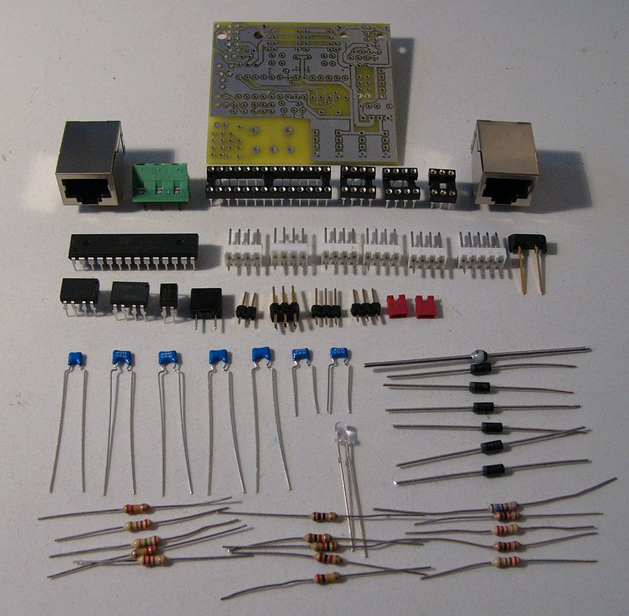
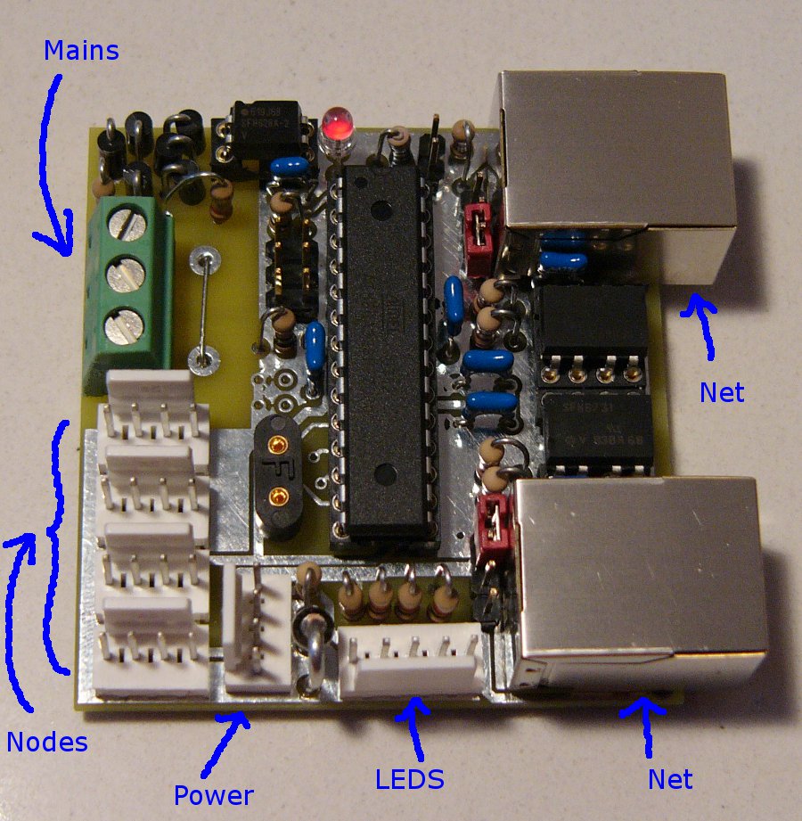
The first module with some intelligence on board. Also here, nothing special when filling up the board. Actually the PCB allows for two different build-ups. In this situation we have chosen for RJ45 jacks. These are not ethernet capable. It only uses the same cable and connectors, because they are cheap. The connection to the mains is to deduce the 50Hz signal (or 60Hz). It is possible to connect up to four actuator nodes. And there is a special connector for leds, indicating the state op the output. You can place a crystal if you like, but in this version we have not.
SenseController
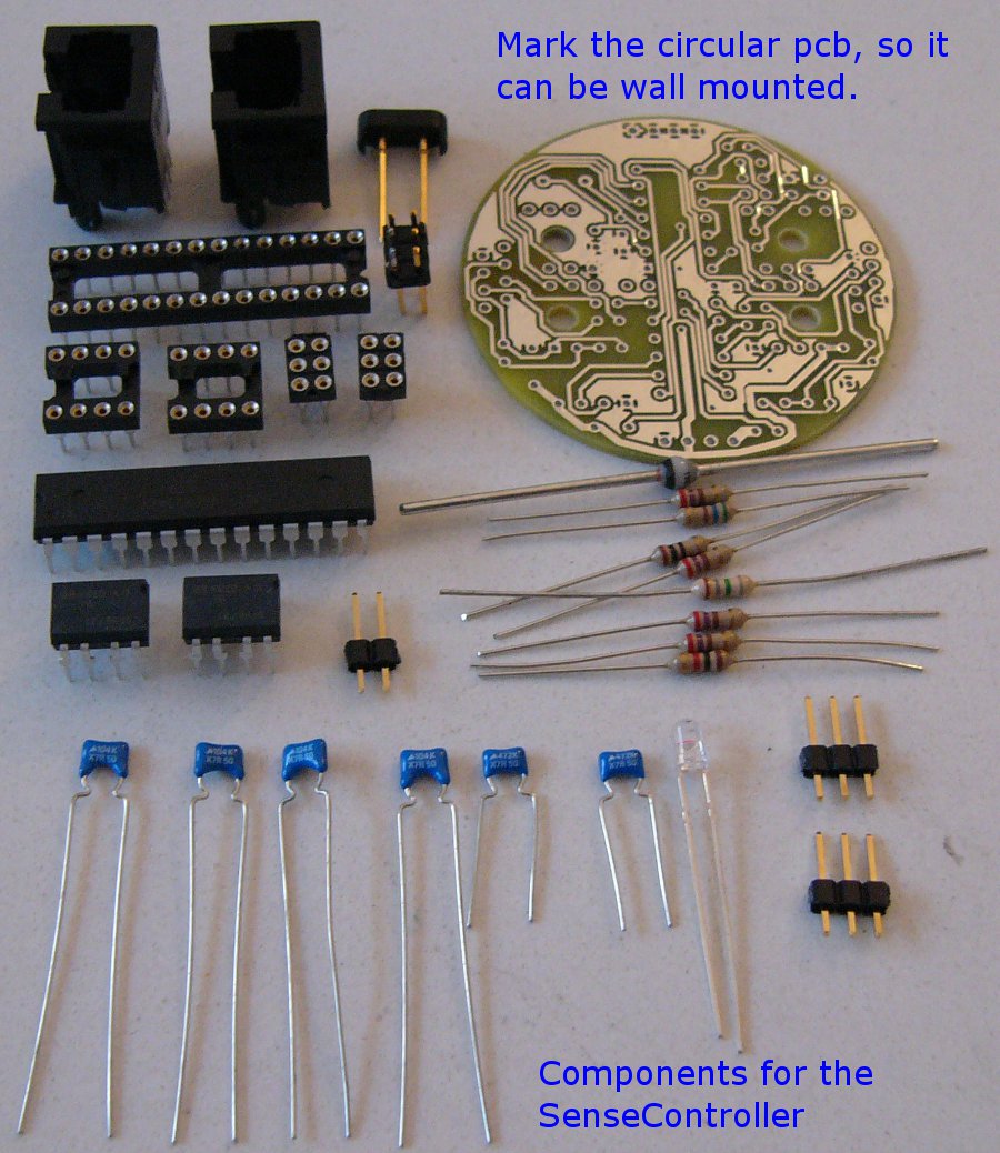
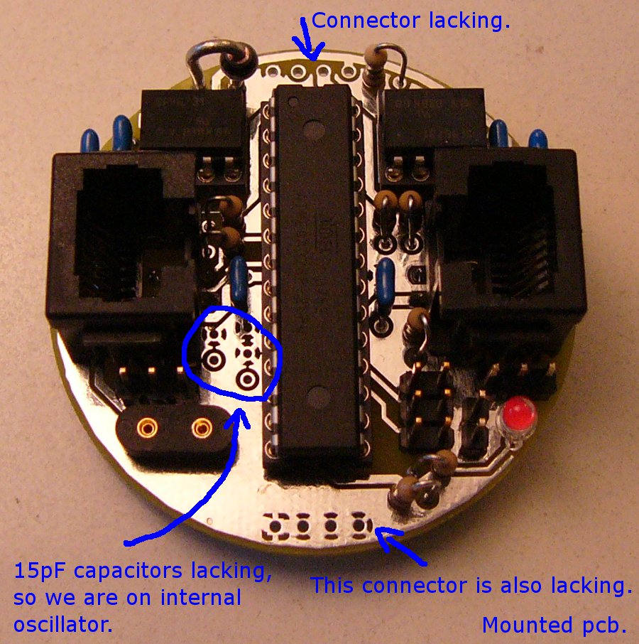
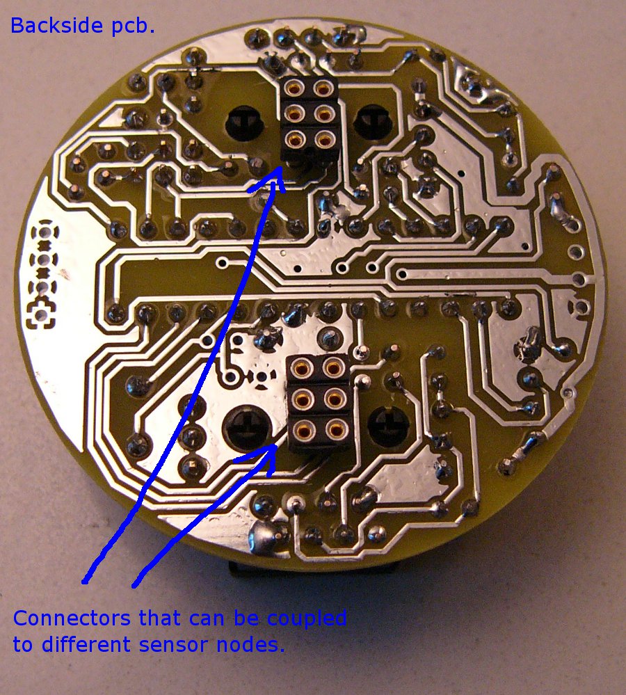
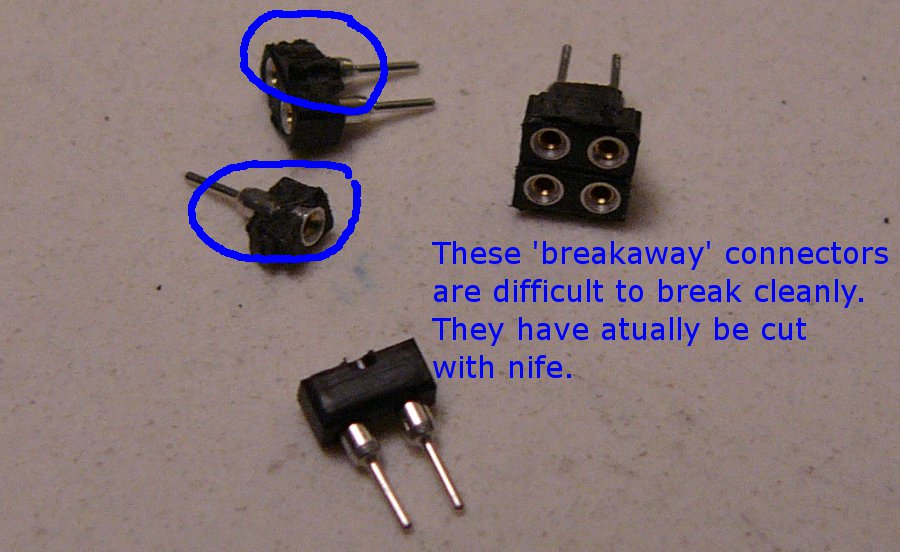
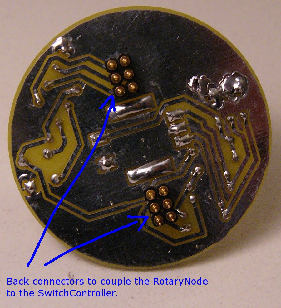
The SenseController is on a circular PCB because it has to fit into the wall. If placed into the wall, it is best to remove the mains from that compartment for safety. Diameter 50mm. At the moment of construction we do not yet have the connectors to fit the MiniPower, but that is not essential to test the system. Observe that we have mounted female pin headers to the other side. This is to stack a RotaryNode or a (future) TouchNode. In this concept you can think of your own type of sensor too, remote control or rfid reader for example.
RotaryNode
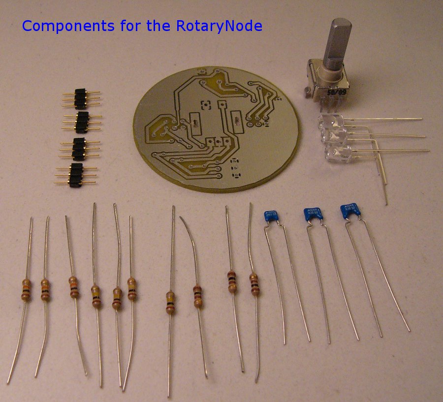
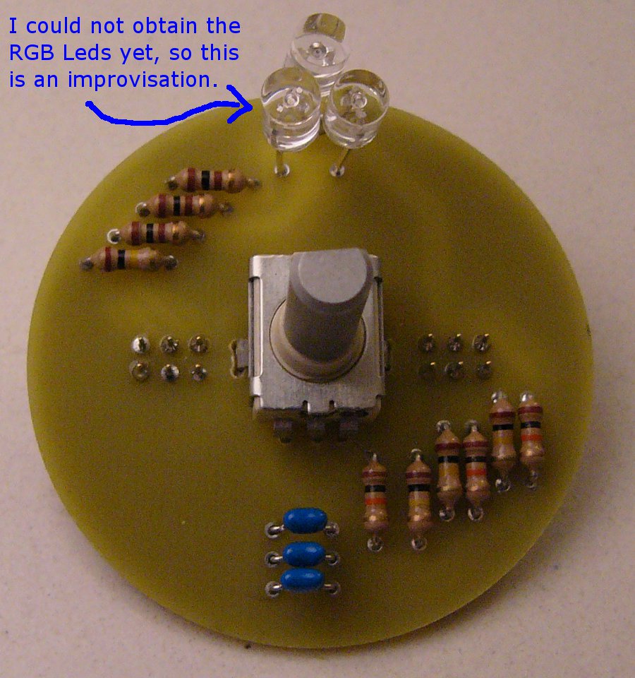
The RotaryNode is an input device. We have chosen for a rotary encoder with push function. This enables versatile inputs, while being simple to operate. As feedback, a RGB led will be used. However, obtaining the right led is not easy. For the moment, we have separated mounted leds. That will do for the testing just fine.
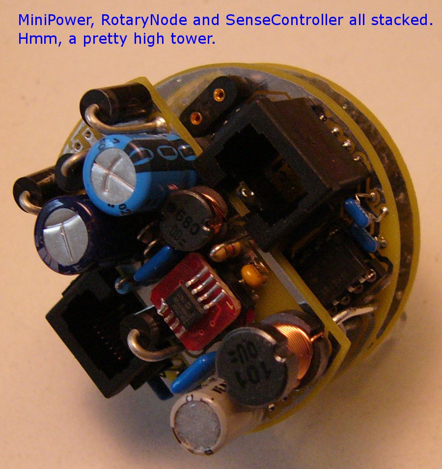
Mounting SenseController and RotaryNode
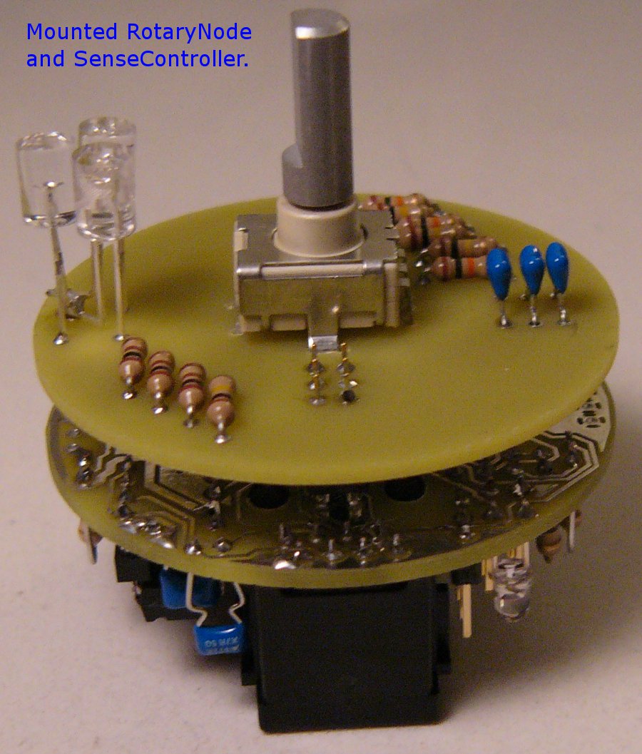
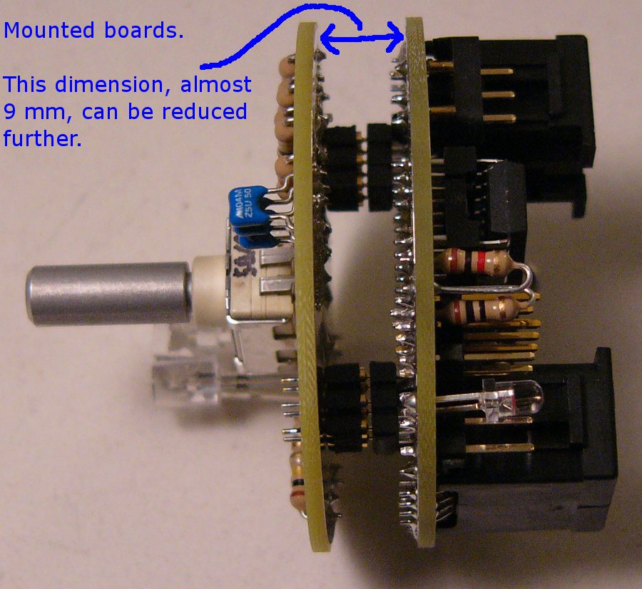
Here we see the stacked PCB's. Although the concept works, the spacing could have been tighter. In the next version I will see if I can order other components. Another problem is that the rotary encorder does not have a screwthread, so we cannot fix it. Hmm, how are we going to solve this?
All together.
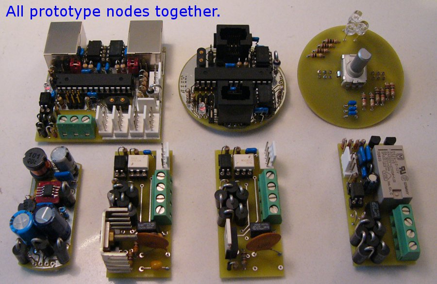
Here are all mounted PCB's together. Mounting one PCB costs about one to two hours, if you have some experience. Of course, since these are prototypes, we had some extra difficulties to overcome. But the end result is quite neat. The dimensions are: Circular PCB (SenseController and RotaryNode): diameter 50 mm, MiniPower: 22mmx50mm (circular edge), RelayNode, SwitchNode and DimNode: 57x25mm and ActController: 57x55mm.
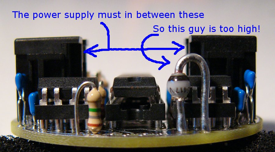
Does it fit?
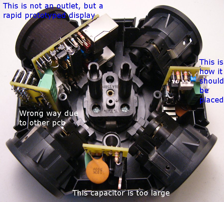
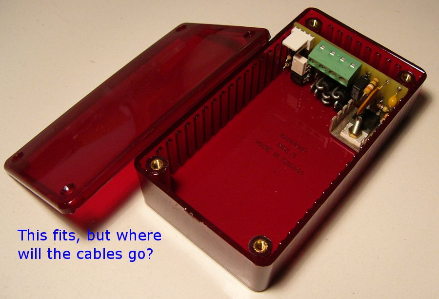
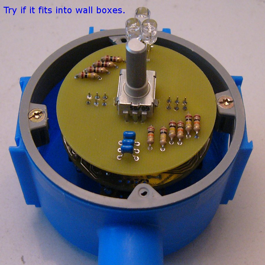
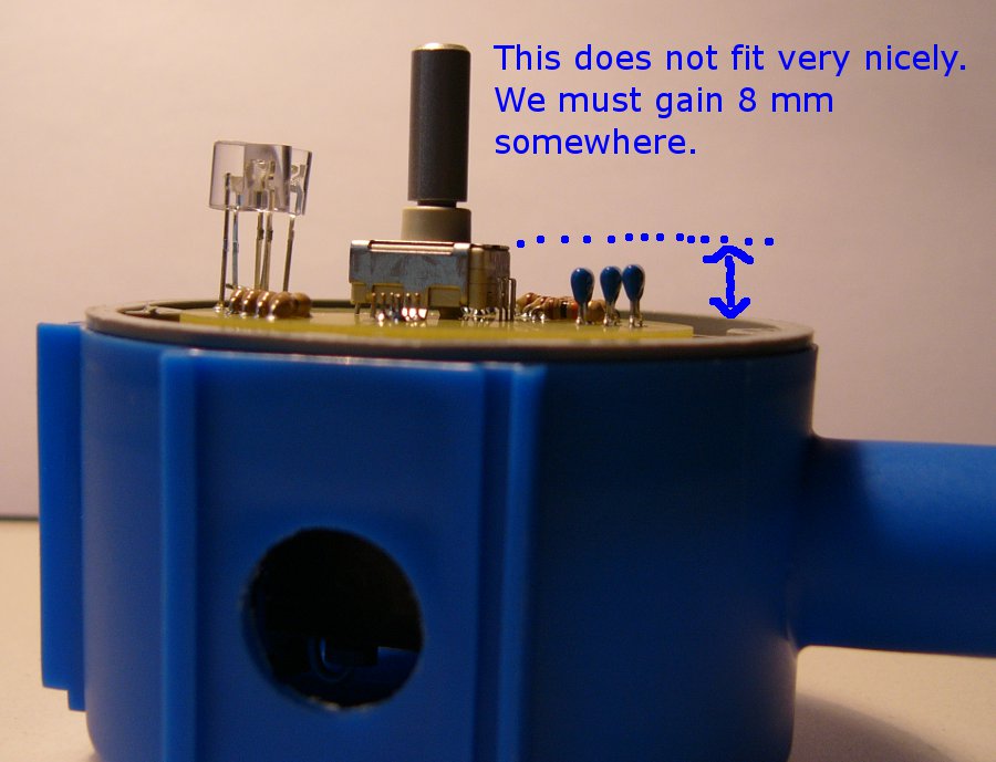
OK, moment supreme. Does it fit the casings I had in mind? We see there are still some problems that have to be dealt with. The sensor part is too high when the mini-power is mounted. So we have to work with 5V= over the cable (which is possible) and locate the power supply somewhere else (where?) or we have to redesign the minipower. (see discussion at the MiniPower node). The red box is clearly to small for the job (i do not have the illusion these devices can be mounted inside the mains outlet. That would only be possible with factory-made smd electronics. In my home I have a different kind of outlet on several locations, with a lot of space inside. The PCB's fit (actually in this situation I would not use these RJ45 jacks) but some adjustments have to be made. For other operations (normal outlet) I will come with proposals next time.
The Conclusion
The prototypes are not bad, for a first try at least. With a few adjustments to the PCB and a few different (smaller) components, everything will work out well. Next time we will go into detail about the electronics and software.
| Contact: info@templetronics.org | CC-BY-NC-SA License: Ruud Vlaming. |